Home/office renewable energy
A case study
The solar and electrical installation
|
Home/office renewable energy A case study The solar and electrical installation |
|
|
On October 22, 2000 we flipped the switch on phase one of our new alternative electricity supply system. This first step involved solar panels, batteries and current inverter and is described below. The second major phase was the installation of a wind turbine which began generating electricity at the end of October, 2004. |
Why are we investing in renewables? |
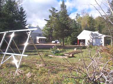
| This view shows the relationship between the house, workshop and solar panel array. All the alternative energy equipment will be installed in the workshop and the power fed underground to the house. The panel rack in the foreground is just sitting on the ground, not yet mounted.
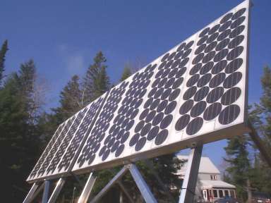
Adjustment of angle is done by using different bolt holes at the top of the rear supports. Too crude and slow. We'll be fixing that later. |
 |
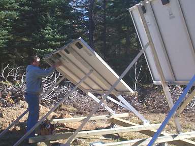
| This is our solar system specialist, Jason Elliott wiring up the photovoltaic array. He is highly skilled and did virtually the entire electrical installation in a single day. I was exhausted and I mostly just stood around and helped when I could.
There are eight SR100 Seimans 100 watt panels. They will not be nearly enough to power our needs, which includes the household and two offices. A wind turbine will complete the system, although we can't rule out another bank of solar cells. |
 |
| The trench is about 18" deep. It leads from the solar array, past the utility pole that brings grid electricity, to the back corner of the workshop. The electrical cable is enclosed in flexible foundation drainage pipe to protect it from rocks in the soil that shift around because of frost action. | 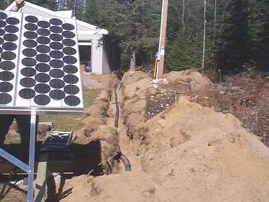 |
| Here are the eight six volt Surrette batteries, wired in series to put out 48 volts. They have a capacity of 820 amp-hours. These monsters weigh 320 pounds each! The battery box is insulated because the shop is not heated full time. We try to keep the batteries above 10°C. Early indications were that this wouldn't be a big problem, since the batteries make some heat as they work. However, once the wind turbine was installed and we charged them less from grid, their temperature fell too low in winter. I now have to figure out a way to heat them. The box is vented to the attic. | 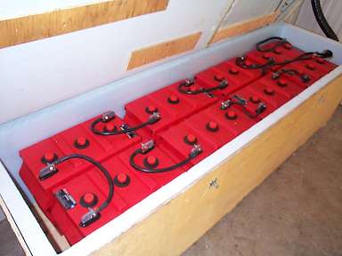 |
| This is the inverter and associated components mounted but not yet fully wired. The cord plugged into the wall was installed as an interim step just to get the batteries on charge. | 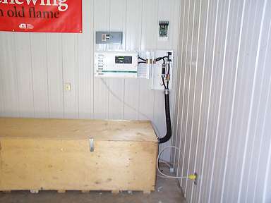 |
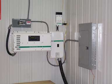
| This is the complete power panel. The gray panel on the right is 110 V supply from the grid. The small white box at the top centre is the charge controller that receives power from the solar panels. The big white horizontal box is the Trace 4855 inverter that converts 48VDC to 110VAC and manages charging. The 110VAC cable to the house goes straight up from the gray inverter bypass switch box.
We bought all the hardware from Renewable Energy of Plum Hollow in Kingston, Ontario Chuck Gobeil and his colleagues were very helpful to us as we started this process. |
 |
| This meter is mounted in the main hallway of the house. It tells us percentage of battery capacity left, actual battery volts, real time current draw, and total amp-hours drawn from the battery bank since the last full charge. The -12.5 (DC amps at 48 V) current shown here was the result of two computers a couple of lights and the fridge running. This is a high current draw of the kind we'll have to reduce in order to be self-sufficient. On a sunny day this real time current draw will go positive because it is the net of inputs and outputs to the batteries. Yes, that is a little yellow happy sun face. | 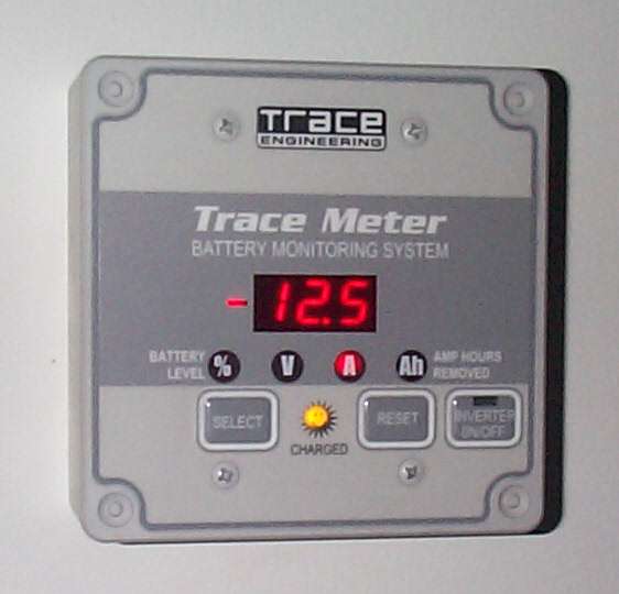 |