Home/office renewable energy
A case study
Heating the shop and battery enclosure
|
Home/office renewable energy A case study Heating the shop and battery enclosure |
|
|
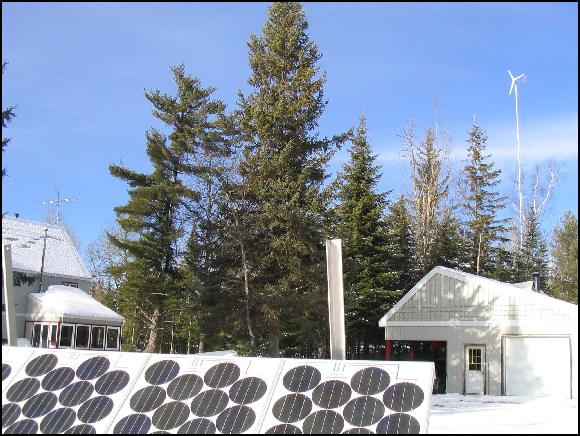
It all started with the decision to locate the renewable electric hardware in the shop rather than in the house. That decision led to the batteries getting cold because the shop is not heated every day in winter. Cold batteries are inefficient batteries, which started me thinking of ways to keep them warm. After much consideration, I decided to build a tiny boiler and run the resulting hot water through in-floor radiant tubing inside the battery box. The decision was simple, the execution of it was not. The project took a year from start to finish. |
Why
are we investing in renewables? |
|
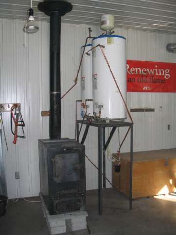
Here is an overview of the installation showing the boiler, water
storage tanks and part of the battery enclosure. The tanks are recycled
gas water heaters totalling about 70 gallons. A single circ pump moves
water through the boiler and through the heating coils in the
floor of the battery enclosure. The system works fine. Once it was finally completed, I was able to raise the battery temperature from 8°C to 22°C in a day, which is good considering that the batteries are so massive. Each one weighs 320 pounds and there are eight of them. Last winter the bank of batteries got very cold, down to near freezing, and there was little I could do about it. The heat loss from the boiler cabinet is just barely able to heat the shop, so the balance between heating air and water is fairly good. I might add a fan-coil unit later so I can heat the shop faster. |
|
|
Here is a front cross-sectional drawing of the boiler, with the access
doors and primary air inlets ghosted in. The two semi-triangular blocks
forming the floor of the firebox are custom refractory castings. I had to
build an elaborate mold for these, with a central duct for secondary air
and ten 3/16" air holes from the duct into the slot between the
blocks. The blocks are formed so there is a 1" space 11" long
which forms the slot through which the exhaust flows down into the
secondary combustion zone.
I produced a drawing for each of the steel components and had them cut and bent by a local company. I did the welding assembly myself. Ever since I built a couple of downdraft stoves back in the 1970s, I've had a soft spot for downdraft combustion. Part of the reason I built such an elaborate shop heater was so I could play around with a downdraft. I've really enjoyed it so far. |
|
|
Here is a side cross-section. A couple of things are worth noting here.
First, there is the bypass damper to allow updraft combustion to get the
thing started and for loading. Building a one-off damper like that is not
a lot of fun. It is also the most vulnerable part of the boiler. I'll be
watching to see how it stands up, but I've already decided how to change
it if it gets warped from too much heat. So far, so good.
Second, note that the front panel is two layers, which forms a 1" plenum through which the combustion air flows. The upper chamber of the plenum feeds the primary air tubes over the door. The lower chamber feeds the secondary air through the refractory blocks at the base of the firebox. The plenum uses heat released through the front to pre-heat the combustion air. The water tube heat exchanger (not shown) has 14 vertical steel tubes welded to top and bottom manifolds. It was not easy to build for a hack welder like me. Unfortunately, I didn't photograph it before it was installed. |
|
|
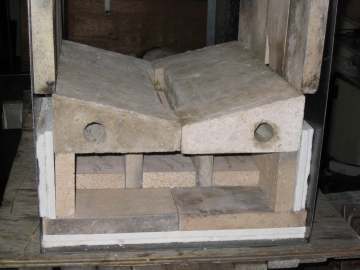
Here is a shot of the core as I mocked it up for fit. Except for the two
refractory castings, the core is made up of firebrick splits.
The white material below and beside the bricks is Kaowool, a fiber refractory material; the pieces shown are not complete, but are just for dimension. In the final assembly the core was surrounded by 1" of Kaowool, made up of 1/2" of blanket and 1/2" of soft board. The idea is to get the core very hot and to limit heat loss from the core to the outer cabinet. The centre passage is blocked at the back, which forces the exhaust forward, around the two rows of bricks on edge, and out the back to the heat exchange section through the two outer passages. |
|
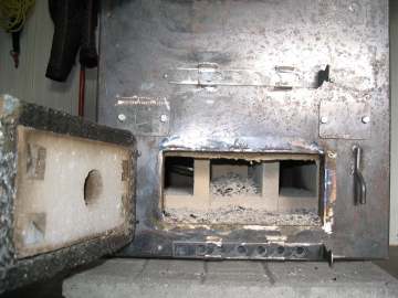
| Here is a view of the core through the ash door. Note that the door is lined with Kaowool to retain heat and protect the steel from the intense heat. I used cotter pins through small squares of stainless steel sheet to hold all the Kaowool panels in place, a method I've used with success on other projects in the past. |
|
|
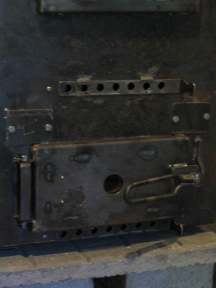
Here is a pic of the lower door showing the primary and secondary
combustion air controls and the viewing port. I have now added a small
combustion air fan to the secondary air inlet under the lower door. The door handles never get
too hot to touch.
The two covers at the top corners of the door provide access to the air ducts at the ends of the refractory blocks. Access was needed during assembly to create the seal between the cast blocks and the steel cabinet shell. |
|
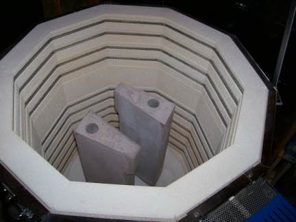
| Here is a pair of replacement refractory castings just before they were removed from a friend's pottery kiln. The first ones broke when I tried to remove them to reseal the joints at the front and back of the firebox. The originals hadn't been fired this way. The second ones were much harder after firing. If you tapped them with something metal they would ring like a wine glass. These ones have been used to two years and they still have sharp edges like new. |
|
|
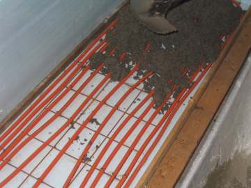
Here is the concrete being placed over the 'PEX' tubing inside the battery
enclosure. The enclosure is only 24" x 91" and yet I was able to
stuff almost 90 feet of tubing into it.
Although I had heated the shop through the first half of the 2005-2006 winter with the boiler without the heat exchanger or battery heating loop, the full system was finally completed and put into service on February 6, 2006. |
|
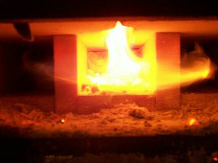
| Here is a picture taken with the lower door open. The refractories are not just lit up by the flames, they are glowing red on their own. The reason downdrafts burn clean when they are set up right is that these chambers and ducts under the firebox are insulated and are a great environment for combustible wood gases to burn in. |
|