|
Note: This book was written in 1996 - 97 during a period when housing technologists across North America were expressing alarm about the potential for house depressurization to cause smoke spillage from wood burning systems. These concerns were reflected in restrictive building code provisions in some regions. Now, with more than three decades of experience with tight houses, large exhaust devices and wood heating equipment, it is clear that the concerns were largely misplaced. While it is true that some houses can be seriously depressurized by their exhaust fans, most homeowners are able to manage the conflict by not using large exhausts when their wood burner is operating.
Effective make-up air systemsThe two common strategies used in the attempt to ensure safe chimney venting in tight houses — passive make-up and direct-to-combustion chamber air supplies — have been shown to be unreliable. Neither approach can consistently prevent combustion spillage when mechanical exhausts cause excessive depressurization of the building envelope. These findings raise the question: What design or remedial measure can be used in a house that can be depressurized more than the fireplace or stove can tolerate? One answer is to force make-up air into the house at the right time and in the correct volume to bring the pressure back closer to neutral. Most houses do not need make-up air systems to prevent the failure of chimney vented combustion systems. Assuming a system of good design, reliable chimney venting occurs when:
A make-up air system may be required if one or more of the characteristics above are not present, ie. an open appliance and/or a very powerful exhaust ventilator and/or an extremely tight building envelope. The first two characteristics can be observed, but the degree of airtightness of the envelope must be established by testing. When you encounter a house with an exhaust-only ventilation system that is causing venting failure, the only effective strategy is to replace it with a balanced system. If the house pressure test results show that exhaust devices can cause more depressurization than can be tolerated by the fireplace, a powered make-up air system can be installed. Forcing make-up air into the building with a fan is necessary because passive make-up air systems are unreliable and impractical.
In houses with forced-air heatingIn a house with a forced-air heating system, the furnace fan and distribution ductwork can be used to drive the flow of incoming make-up air, temper it and distribute it throughout the house. This approach involves connecting an air supply duct between the outdoors and the main cold air duct upstream of the furnace blower cabinet. A tight fitting, motorized damper in the make-up air duct is interlocked with the switches of the largest exhaust ventilator and the furnace fan. The system is activated when the largest exhaust (usually the kitchen range exhaust) is turned on, which in turn causes the furnace fan to start and the make-up air damper to open. The negative pressure in the return duct causes make-up air to flow through the duct into the return system where it is tempered by mixing with the circulation air and distributed throughout the house. A standard 24 volt AC step-down transformer is needed to convert the line voltage of the kitchen exhaust fan circuit to the low voltage of the make-up air duct damper. This electrical wiring should be subcontracted to a qualified electrician. The volume of flow through the duct is determined by the extent of negative pressure in the cold air system and the diameter and configuration of the make-up air supply duct. The problem of return air duct system leakage discussed earlier is a key issue to consider when evaluating the installation of this type of make-up air system. If the negative pressure developed in the cold air ducts is low and/or if the operation of the furnace fan depressurizes the basement or utility room, check for leaking joist lined or panned ducts. Sealing the leaks can help to increase the driving pressure in the duct and reduce the fan effect on room pressure. Using a forced-air heating system to drive make-up airThe illustration below shows one example of the necessary components and how they can be arranged.
Notes:
Cold climate caution: The objective in designing a make-up air system coupled to a forced-air heating system, particularly in cold climate zones, is to bring in as little outdoor air as possible. This is because a large volume of cold outdoor air can cause thermal shock to the furnace heat exchanger or condensation of furnace exhaust gases. With this type of system, flows greater than 200 CFM should be avoided, unless a supplementary duct heater is added to the system to temper the cold incoming air. The heater can be controlled by a thermostat so that it is activated only when necessary.
Using a duct heater/fan assembly *
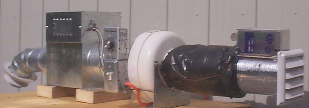
* installation should be subcontracted to a HVAC specialist Here is a picture of a make up air system mock-up used for classroom training similar to the illustration above. In the photo, the air flow direction is from right to left.
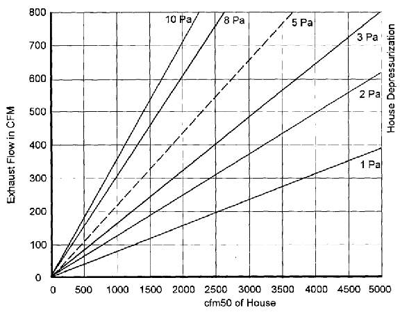
In a house without forced-air heating, an electric duct heater with a fan can be used to drive the flow of air and temper it to a comfortable temperature. A diffuser grille located at ceiling level is normally used to disperse the incoming air and to minimize cold air pooling at floor level. This type of installation should be handled by a qualified heating contractor. See the illustration above for its general configuration. Sizing make-up air suppliesThe most accurate way to determine how much make-up air is needed to reduce envelope depressurization by a specific amount is to test the house using the fan depressurization method (blower door). This method can yield a measurement of the actual make-up air requirement. However, if this test is not being done on the house for other reasons, the cost is not likely justified. Without such equipment, it is unwise to attempt excessive precision because you could unintentionally create a system that is unable to deliver sufficient make-up air. Ideally, the make-up air system is designed to be slightly larger than necessary so that it can be adjusted downward to provide the correct flow. The approximate volume of make-up air that must be supplied can be inferred by using Tables 2 and 3 (repeated below for convenience) in combination with the results of the simplified house pressure test. Table 2 provides the estimated air flow of the exhaust devices that are primarily causing the excess depressurization, Table 3 provides insights into the relationships between flow and pressure in houses with various degrees of leakiness, and the house pressure test tells you exactly how the house pressure is affected by the exhaust flows. Table 6 below provides the estimated air flows for standard powered make-up air systems of the types illustrated here. Here is an example of how Tables 2 and 3 (reproduced below) and the house pressure test can be used as aids in the design of an effective powered make-up air system. A house contains a factory-built fireplace that can tolerate a depressurization level of 5 Pa. The house pressure test reveals that the clothes dryer causes a 2 Pa depressurization when operating alone and the house pressure changes to -7 Pa when the kitchen range hood exhaust is turned on. From Table 2 it is determined that the total exhaust from these two devices is in the range of:
We will use 270 CFM as the worst-case exhaust flow condition. In Table 3, we find that an exhaust flow of 270 CFM produces a 7 Pa depressurization (from the pressure test) in a house with a CFM50 of about 950. By looking down to the 5 Pa line on the chart, we determine that an exhaust flow of 200 CFM could be tolerated. The necessary make-up air flow would be:
To determine the size of make-up air system required, the negative pressure in the cold air return system is measured. In this example, the return pressure is -20 Pa. Using Table 6 below, we find that a 6 inch system of the type illustrated will flow 68 CFM and that a 7 inch system would flow 102 CFM at a 20 Pa driving pressure. The technician carrying out the modifications might decide boost the return air pressure to -25 Pa by sealing leaks and slightly increasing the fan speed. At 25 Pa driving pressure, a 6 inch system will flow 74 CFM. If, on the other hand, the actual design of the make-up air system is more complicated than the one illustrated, or if flex duct is used, it would be wise to go with a 7 inch system. In this example, we used the worst-case estimate of exhaust flow from Table 2 and the safest permissible flow from Table 3, so our make-up air system will be able to flow somewhat more air than we need to maintain the house pressure at or above -5 Pa. Following on with our example, when the make-up air system installation is completed, the house pressure test is repeated to confirm that the depressurization level is reduced to a level that can be tolerated by the fireplace. The second house pressure test shows that with its manual damper fully open, the make-up air system reduces the depressurization level to 3 Pa. With more air being delivered than necessary, the manual damper in the make-up air duct is adjusted so that, with the clothes dryer and kitchen range hood exhaust operating, the depressurization is reduced to -5 Pa. This procedure ensures that the house cannot become depressurized to the extent that it compromises the operation of the fireplace, yet only the minimum necessary amount of make-up air is delivered to the house. Table 6.
|
|||||||||||||||||||||||||||||||||||||||||||||||||||||||||||||||||||||||||||||||||||||||||||||||||||||||||
|
Cold |
|
|
|
|
|
|
air duct |
Diameter of make-up air assembly* |
||||
|
pressure |
4" |
5" |
6" |
7" |
8" |
|
5 |
6 (13) |
9 (19) |
16 (34) |
20 (42) |
34 (72) |
|
10 |
9 (19) |
15 (32) |
22 (47) |
33 (70) |
48 (102) |
|
15 |
11 (23) |
18 (38) |
27 (57) |
40 (85) |
58 (123) |
|
20 |
13 (28) |
21 (45) |
32 (68) |
48 (102) |
68 (144) |
|
25 |
15 (32) |
24 (51) |
35 (74) |
54 (114) |
77 (163) |
|
30 |
17 (36) |
26 (55) |
38 (81) |
59 (125) |
85 (180) |
|
35 |
18 (38) |
28 (59) |
42 (89) |
64 (136) |
91 (193) |
|
40 |
20 (42) |
31 (66) |
44 (93) |
68 (144) |
98 (208) |
* This table assumes that the make-up air supply has the following characteristics:
- 10 ft in total length of rigid duct (increase one size for flex duct)
- one 90 degree elbow
- one key damper and one motorized damper
- sealed connection with furnace cold air return duct
The spillage test is a useful tool, both for predicting the performance of a fireplace in a new home and for diagnosing the cause of venting failure in an existing system.
You can download a handy spillage test report form in Microsoft Word format.
Table 2 and table 3 from the chapter on The effects of powered exhausts are reproduced here for your convenience.
Table 2.Estimated air flows of typical intermittent exhaust devices
|
Device |
L/s* |
cfm* |
|
bathroom fan |
15 - 30 |
30 - 60 |
|
standard kitchen range hood |
40 - 60 |
80 - 120 |
|
downdraft bbq range exhaust |
100 -300 |
200 - 600 |
|
clothes dryer |
40 - 75 |
80 - 150 |
|
central vacuum |
25 - 60 |
50 - 120 |
Average airflows of chimney vented combustion systems
|
chimney vented oil furnace |
40 - 75 |
80 - 150 |
|
B-vented gas furnace |
40 - 60 |
80 - 120 |
|
B-vented gas fireplace |
30 - 50 |
60 - 100 |
|
open wood/gas fireplace |
80 - 300 |
160 - 600 |
|
wood fireplace with doors |
30 - 50 |
60 - 100 |
|
wood heater |
5 - 15 |
10 - 30 |
|
masonry heater, burning wood |
20 - 30 |
40 - 60 |
*L/s is litres per second; cfm is cubic feet per minute. The figures in the table have been rounded off.
Table 3. House depressurization chart
Back to the Table of Contents