|
Susceptibility to combustion spillage can be affected by the design of the venting system. The system is made up of the chimney and, in the case of stoves, the flue pipe assembly. Fireplace and stove owners commonly blame smoking and other malfunctions on the appliance itself. But in in the majority of cases, it is the design and location of the venting system that is the source of problems. Here is a review of the characteristics of the venting system that can affect hearth performance.
As you have learned, the temperature difference between the air and/or combustion gas in the venting system and the outdoor air produces the key driving pressure in natural draft systems. Therefore, chimneys that minimize heat loss tend to perform better because they maintain a higher average flue gas temperature and produce more draft.
| A useful analogy when considering the functional characteristics of chimneys is to view the chimney as the engine that drives the system. Think of heat as the fuel for the engine and think of draft as its power output. The more heat (fuel) that is delivered to the engine, the more draft (power) it will produce. Any loss of heat from the engine itself is wasted fuel that detracts from its potential power output. |
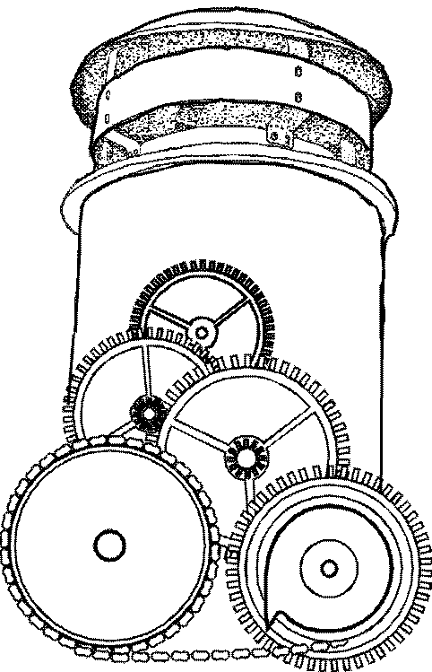
The chimney is the "engine" that drives the combustion system.
|
Theoretically therefore, the best chimney is one that insulates the flue gas passage perfectly, losing no heat to the outside. Such a chimney would maintain the highest possible average gas temperature from bottom to top. In practical terms, however, a perfect chimney might require the use of exotic materials and could be very expensive. So, given the commercial and practical limitations, how do modern chimneys stack up against perfection?
The vast majority of modern chimneys fall into three categories: masonry chimneys, solid-pack insulated metal chimneys, and double- or triple-wall, air-cooled metal chimneys.
Conventional masonry chimneys
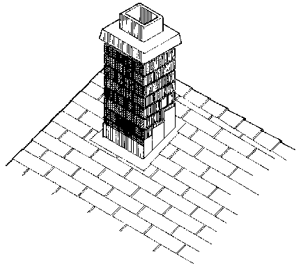 |
Conventional masonry chimneys consist of a clay tile flue liner surrounded by an outer shell of brick, block or stone. The flue liner is not insulated and the masonry materials themselves are not particularly good insulators. The massive construction and lack of insulation means it is slow to develop draft as the initial flue gas heat is absorbed into the masonry. On the other hand, when the fire recedes to a coal bed, draft declines relatively slowly as the stored heat is released back into the flue passage (see Energy momentum). During tail-out phase of the fire, the surface temperature of the flue liner can be higher than the flue gas temperature. |
Solid-pack insulated metal chimneys
Solid-pack insulated metal chimneys consist of a stainless steel flue liner surrounded by a fibrous insulation and a metal outer casing. A solid-pack chimney develops draft very quickly at start-up because the thin liner has little mass and heat transfer to outside is resisted by the insulation. However, the insulation in some models of solid-pack chimney is not particularly effective because part of its function is to draw heat away from the flue liner to prevent it from overheating during extreme high firing or a chimney fire. The solid-pack material acts as a "heat sink" or mass, which explains why a section of solid-pack chimney is relatively heavy considering its small size. This characteristic may help to maintain some draft as the fire recedes because the mass in the chimney gives up stored heat to the flue gases.
|
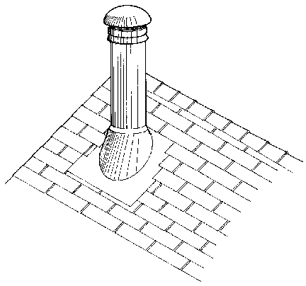
| A factory-built metal chimney (above) and a cross section of solid pack metal chimney (right). |

|
|
Air-cooled, air insulated and hybrid chimneys
| Air space is used either alone or in combination with fiber insulation in a number of chimney designs. Double-wall air-cooled chimneys consist of a stainless steel flue liner, an air space and a metal outer casing. There are openings at the base of the chimney for the entry of cooling air which flows between the liner and casing of each section before being expelled at the top of the chimney under the rain cap. Triple-wall air-cooled chimneys draw cooling air from one part of the special top termination where it flows down to the base of the chimney, around the inner wall and back up the inner passage to exit from another section of the complex chimney cap. Air-cooled chimneys allow flue gas heat to be released faster than masonry or solid-pack metal. The very low mass of an air-cooled chimney means it heats up and develops draft quickly, but it also cools down very quickly. Unlike a masonry or solid-pack chimney, the flue liner in an air-cooled chimney is virtually never at a higher temperature than the flue gases. In general, air-cooled chimneys are used for fireplaces that do not control the rate of combustion to a significant degree. The high flow rates and temperatures characteristic of such fireplaces tend to suit the behavior of air-cooled chimneys. |

Double-wall air-cooled chimney cross section

Tripple-wall air-cooled chimney cross section

Hybrid solid pack air-cooled chimney cross section
|
One serious drawback of air-cooled chimneys is related to the problem of the cold hearth syndrome. Since cold outdoor air circulates through some of these designs, there can be cases in which the air in the chimney is cooled below room temperature, even if the chimney is installed within the building envelope. When this occurs, of course, a cold backdraft is the likely result if the fireplace is installed below the building's neutral pressure plane.
Two hybrid designs use both fiber and air insulation. In one case, a relatively thin layer of fibrous insulation is used around the flue liner and is surrounded by an air space, and in the other case, a thin, sealed air space is maintained between the flue liner and insulation. These types of chimney probably have functional characteristics between that of the solid-pack and air-cooled types.
| While it may be tempting to blame the apparent increase in venting failures on houses that are "too airtight", such a view misses other influences, such as chimney design and location, which can be more significant than airtight housing. Besides, resisting the movement towards energy conservation is not likely to be productive or successful in the long run. |
Going back to our analogy of the chimney as an engine, it is apparent that most modern chimneys do not compare well to perfection. Chimney technology is one aspect of energy use that has not benefited from twenty years of activity in the field of energy conservation. Dramatic reductions in energy consumption have been achieved in virtually every other area: in housing, transportation, industrial process and so on. Efficiency improvements in furnaces, stoves and many fireplaces mean that more of the fuel's heat energy is delivered to the house, resulting in lower flue gas temperatures entering the base of chimneys. Yet the majority of our chimneys continue to waste this precious heat at about the same rate as chimneys did fifty years ago. The relative absence of serious efforts to conserve energy through improved chimney technology, while houses and combustion appliances have changed dramatically, is part of the explanation for the serious venting failures that seem more common today than in the past. |
Flow resistance
Another main design feature of a venting system that can affect spillage is the resistance to flow that the system presents to the stream of exhaust gases. The most common restrictions are:
- elbows and key dampers in flue pipe assemblies, flue dampers in masonry fireplaces,
- baffles in stoves,
- and offsets, creosote deposits and
- undersized flues in chimneys.
Flow resistance in the venting system is most likely to be a factor when the appliance loading door is opened for fuelling. Open door smoke spillage is linked to venting system restrictions because of the higher volume of gas and air that must be vented. When an appliance is operating normally with its door closed, the volume of flow and speed of the flue gases is relatively low, around 3 ft per second (1 m/s). Elbows, offsets or a small flue offer little resistance at this low flow rate. But when the door is opened for loading, the flow rate typically doubles as dilution air is drawn through the opening, and the restrictions begin to have a far greater effect. If the venting system restricts its free flow, a portion of the exhaust gas may spill into the room. The lower the resistance to gas flow, the less likely is the spillage of combustion gases when the loading door is opened.
|
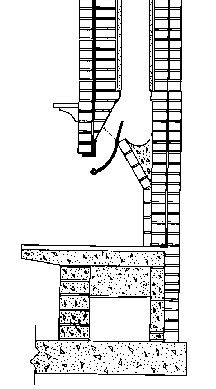
The damper area of a conventional open masonry fireplace is the point of greatest flow resistance because of its shape and size and is one of the main reasons these fireplaces tend to smoke into the room.
|
Air leakage
The amount of air permitted to leak into the venting system affects its performance. There are two ways in which air leakage inhibits performance: first, the leaks bleed off pressure, making less draft available at the appliance; and second, cold air leaking into the flue cools the flue gases, reducing temperature difference and therefore draft.
Flue sizing
A chimney with a flue area that is too small for the volume of gas that must be vented acts as a restriction to flow. Inadequate flue size is a problem only for open fireplaces and for other fireplaces and heaters when their doors are opened for loading. In fact, if it weren't for the need to open doors for loading, fireplaces and heaters could get by with much smaller chimneys than are normally used because of the low gas flow rates involved.
A chimney with a flue area that is larger than necessary also inhibits venting performance, but in a different way. A given volume of flue gas flows slower through a large flue than through a small one, allowing more time for heat to transfer from the gases to the liner. And the larger the flue area, the greater is the flue liner surface area for each unit of length. Therefore, an oversized chimney flue leads to excessive flue gas heat loss, particularly in a chimney with little or no liner insulation. Ideally, flue gases move as quickly as possible through the venting system to minimize the time available for heat transfer to the liner. Flue pipes and chimneys should be sized to match the area of the appliance flue collar if there is one, or, in the case of masonry fireplaces, to the correct ratio between flue area and fireplace opening area.
Combining deficiencies
Venting system design deficiencies can combine to produce extremely poor performance. A common example of this combination of deficiencies is an oversized, outside masonry chimney. In this example:
- the chimney runs up the outside of the house envelope, so it is exposed to outside cold,
- the flue liner in standard masonry construction is not insulated, so there is little resistance to heat loss, and
- a nominal 8" x 12" flue liner is considerably larger in area than the perhaps 6" flue collar of the modern efficient appliance it serves, so heat loss is excessive
In this simple, yet common example, three serious deficiencies are combined in a single system. Note also that the flue gas flows through two 90 degree changes of direction — one in the flue pipe and one in the base of the chimney —that add turbulence and further cooling. This chimney would certainly contribute to poor performance of the combustion/venting system.
Where the venting system includes a flue pipe assembly (chimney connector) it should have the following features:
- it is short
- it has no 90 degree elbows or only one 90 degree elbow; 45 degree elbows are better
- it has no key damper or barometric damper
- its joints fit tightly to reduce leaks
- if excessive heat loss is a concern, sealed double-wall flue pipe can be used
To perform well, the chimney should have the following characteristics:
- it is installed inside the building envelope
- it exits the building envelope at or near its highest point
- insulation surrounds the flue liner
- it has no offset or only a slight (15°) offset
- it has no significant leaks
- its top is not exposed to adverse wind pressures
- it is at least 15 ft. (4.6 m) in height
- the flue area matches the appliance flue collar area
Pellet appliance venting
Pellet appliances have an internal fan that draws air through the combustion chamber and forces the exhaust into the venting system. These automatic feed appliances do not strictly rely on natural draft for successful operation, but some natural draft can help to avoid smoke spillage under some conditions.
| Pellet stoves are not required to vent through a chimney. Instead, a special double wall pipe is used, similar to the B-vent used for gas appliances except that it uses a stainless steel liner. There is no insulation between the two walls of the pipe.
Since they have a powered exhaust system, it was first thought that pellet stoves could just be vented horizontally through the wall. This design works well unless an electrical power failure stops the exhaust fan. Then, the smoke from the small amount of burning fuel seeps out of the stove into the room. This problem has prompted some angry calls from pellet stove owners to the stores that sold them. Battery backup systems are available to keep the fan running for a few minutes and prevent the seeping smoke.
|
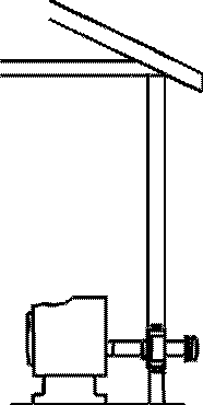
This type of pellet vent installation can result in smoke entering the room during an electrical power failure. It might also be a problem in high winds.
|
|
|
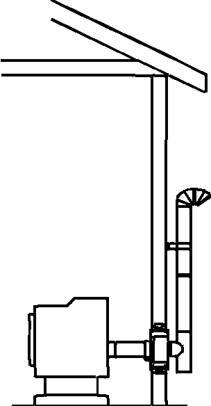
As an alternative to battery backup, some amount of natural draft can be provided so that any remaining combustion products will be vented in case of a power failure. To do this, a few feet of rise was added to the horizontal vent. The idea is that the hot gas in the vertical portion of the vent will create some draft for long enough to burn the remaining fuel in the chamber and vent it outside. This has proved to be a successful strategy for most situations. |
Some locations, however, do not favor horizontal venting of pellet stoves. Experience has shown that houses located on the ocean or other high wind locations, particularly when the vent termination faces into the wind, can suffer from venting failure. When wind creates a high pressure zone on the same wall as the vent termination, the vent pressure from the exhaust fan can be overcome. In moderate cases the result is erratic, dirty combustion, and in severe cases, full backdrafts of exhaust into the home.
The only certain way to deal with the problem of wind is to run the vent up through the roof. The vent termination will still experience wind, but will not experience the velocity pressure produced when wind strikes the wall of a house. The vertical pellet vent installation is the most consistently reliable way to vent a pellet appliance, but it is rarely used because of the additional cost involved.
Summary
- insulated chimneys produce stronger and more reliable draft than uninsulated chimneys
- flow resistance in a venting system increases the likelihood of open door spillage
- air leakage into the venting system should be minimized
- chimney venting systems should exceed 15 ft. (4.6 m) in height
- the chimney flue should be matched in size to the requirements of the appliance it serves
- most chimneys currently available to the public do not posses the characteristics needed for reliable venting
- pellet vents should have some rise to provide natural draft assist to the draft fan; in windy locations pellet appliances should be vented vertically through the roof
|


